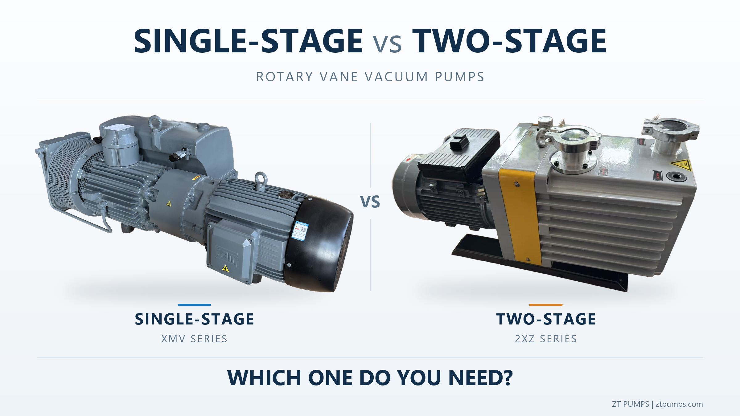
Central Vacuum System vs. Individual Vacuum Pumps: Which Is Better for Multiple Workstations?
Learn when a central vacuum system can outperform individual vacuum pumps in multi-station industrial applications, including energy use, pressure control, piping, redundancy and pump selection.
Short Answer
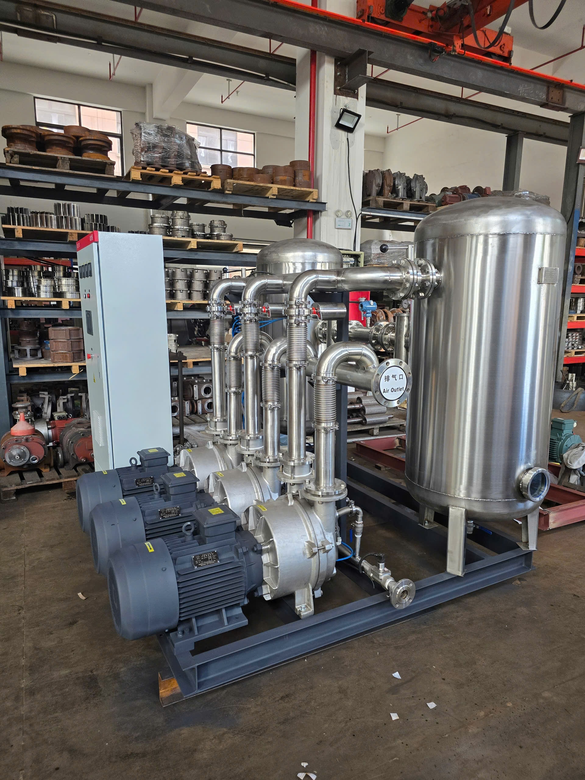
A central vacuum system can be more efficient than installing a separate vacuum source at every workstation when multiple users operate at varying or intermittent loads. Centralization allows several users to share pumping capacity while vacuum generation can be adjusted according to actual demand.
However, centralization is not automatically better. Required absolute pressure, simultaneous airflow, piping losses, leakage, gas composition, duty cycle and redundancy must all be evaluated before selecting the system architecture.
What Changes When Vacuum Generation Is Centralized?
In an individual arrangement, each workstation has its own dedicated vacuum source:
- Workstation 1 → Vacuum Source 1
- Workstation 2 → Vacuum Source 2
- Workstation 3 → Vacuum Source 3
In a centralized arrangement, multiple workstations share a common system:
Multiple Workstations → Branch Piping → Common Vacuum Header → Receiver (if required) → Central Vacuum Station
The engineering question changes fundamentally. Instead of asking:
"What pump does each machine need?"
The question becomes:
"What absolute pressure and pumping capacity does the entire process require simultaneously?"
This shift in perspective is important. The central system must be sized for the actual combined demand — not simply the sum of all individual pump nameplate ratings.
Why Individual Vacuum Pumps Can Consume More Energy Than Necessary
When each workstation has its own dedicated vacuum pump, each pump typically runs continuously regardless of whether its workstation is actively using vacuum. If workstations operate intermittently or at varying loads, each pump still consumes power during idle periods.
This is the load diversity argument for centralization: if not all workstations require maximum airflow simultaneously, a shared central system may be able to serve the same process with less total installed power running at any given time.
However, actual energy performance depends on many factors:
- Operating pressure and pump efficiency at that pressure
- Actual simultaneous demand across all workstations
- Duty cycle of each workstation
- Leakage in the distribution system
- Piping pressure loss from the central station to each workstation
- Control strategy (on/off, staged, VFD)
Do not assume that centralization always saves energy. If all workstations operate simultaneously at full load, a central system may offer little advantage over individual pumps. The calculation must reflect the actual process.
How a Central Vacuum System Follows Process Demand
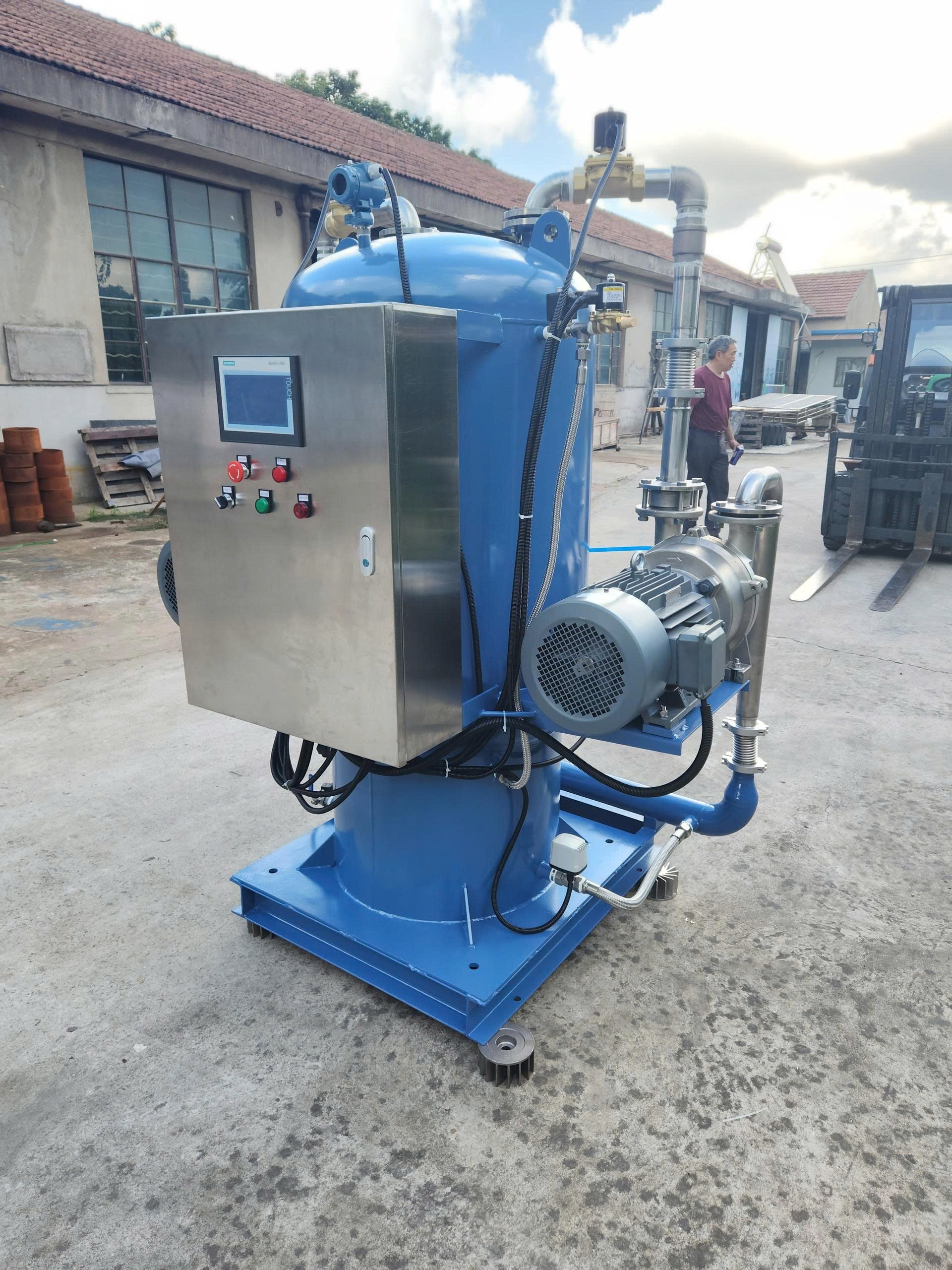
A well-designed central vacuum system uses pressure measurement to coordinate vacuum generation with changing demand:
Pressure Transmitter → PLC/Controller → Pump Control/Sequencing → Common Vacuum Header
When demand increases and header pressure rises (vacuum level decreases), the controller starts additional pumps or increases pump speed. When demand falls, pumps are staged off or slowed.
Common control features in multi-pump central vacuum systems include:
- Staged operation: pumps start and stop in sequence as demand changes
- Lead/lag sequencing: distributes runtime across multiple pumps to equalize wear
- Automatic duty rotation: periodically rotates which pump is the lead unit
- VFD control: on one or more pumps, allows continuous speed adjustment to match demand precisely
- Standby pumps: one or more pumps held in reserve for redundancy or peak demand
- Minimum run time: prevents short-cycling that can damage motors
- Alarms and motor protection: monitors pressure, temperature, current and other parameters
Important: Installing a pressure transmitter alone does not constitute a complete control system. Proper pump sequencing, protection logic, interlocks and alarm handling require a correctly specified and commissioned control system.
Central Vacuum System vs. Individual Vacuum Pumps
| Factor | Individual Pumps | Central Vacuum System |
|---|---|---|
| Installation | Distributed, simpler per unit | Centralized, requires piping network |
| Load sharing | None — each pump serves one user | Multiple users share capacity |
| Maintenance | Distributed across many locations | Concentrated in one location |
| Piping | Short runs, minimal pressure loss | Longer distribution, pressure loss must be calculated |
| Pressure control | Each pump controls its own workstation | Common header pressure controlled centrally |
| Redundancy | Each workstation independent | Standby pumps can cover failures; single-point risk if not designed correctly |
| Noise and heat | Distributed near operators | Concentrated in a dedicated plant room |
| Energy-saving potential | Limited when pumps idle continuously | May reduce energy if load diversity is significant |
| Process isolation | Natural — each workstation isolated | Requires isolation valves if cross-contamination is a concern |
| Expansion | Add a pump per new workstation | May accommodate additional users within existing capacity |
Neither architecture is universally better. The correct choice depends on the specific process requirements, facility layout and operational profile.
Pressure Matters: Gauge Pressure vs. Absolute Pressure
This distinction is technically important and frequently misunderstood.
Gauge pressure is measured relative to local atmospheric pressure. A vacuum gauge reading of −3,000 mmAq means the pressure is 3,000 mmAq (approximately 29.4 kPa) below local atmospheric pressure.
Absolute pressure is measured relative to a perfect vacuum (zero pressure). It equals local atmospheric pressure minus the gauge vacuum.
Using an atmospheric pressure of approximately 101.3 kPa(abs) as a reference:
| Gauge Vacuum | Approximate Absolute Pressure |
|---|---|
| −2,000 mmAq ≈ −19.6 kPa(g) | ≈ 81.7 kPa(abs) |
| −3,000 mmAq ≈ −29.4 kPa(g) | ≈ 71.9 kPa(abs) |
| −3,500 mmAq ≈ −34.3 kPa(g) | ≈ 67.0 kPa(abs) |
These absolute-pressure values assume approximately 101.3 kPa atmospheric pressure. Actual atmospheric pressure varies with altitude and weather. At higher altitudes, local atmospheric pressure is lower, and the same gauge vacuum reading corresponds to a lower absolute pressure.
A critical point: −3,000 mmAq does NOT mean 29.4 kPa absolute. It means approximately 29.4 kPa below local atmospheric pressure.
For vacuum pump selection, specifying operating pressure in kPa(abs), mbar(abs) or Pa(abs) is strongly recommended wherever possible. This removes ambiguity about the atmospheric pressure reference and allows direct comparison with pump performance curves, which are typically plotted against absolute suction pressure.
Practical Example: Multiple Vacuum Users in One Production Facility
Example 1 — Industrial process application
An industrial production facility originally used individual vacuum sources at multiple workstations. Each workstation had its own dedicated vacuum pump sized for its individual peak demand. The pumps ran continuously during production shifts.
The system was later evaluated as a candidate for centralization because the workstations did not all require maximum airflow simultaneously. The evaluation considered actual simultaneous demand, required absolute pressure at each workstation, piping layout and leakage. The engineering calculation — not a simple addition of existing pump capacities — determined whether centralization was technically and economically justified.
Example 2 — Material handling application
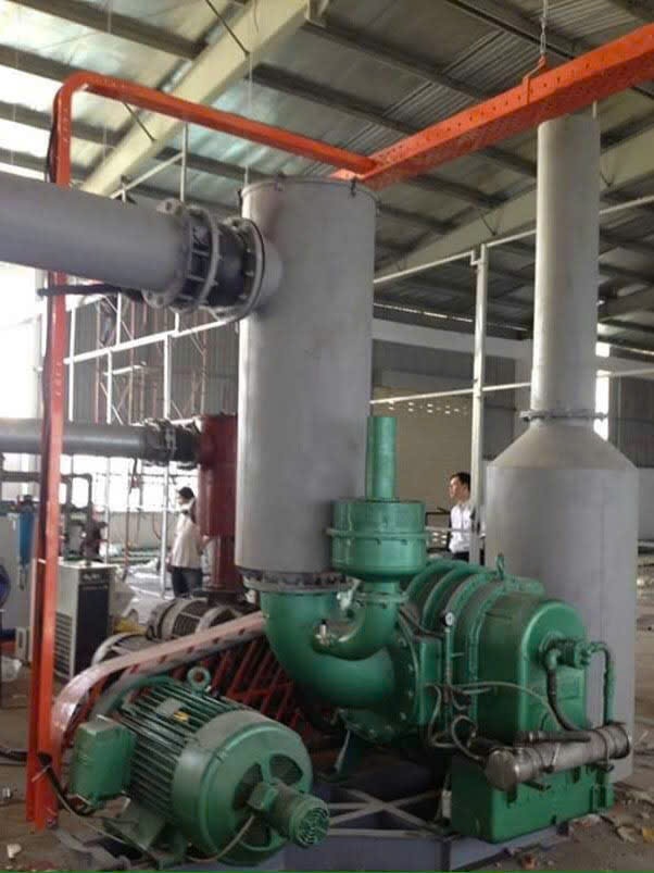
Engineering experience: In a previous multi-workstation material-handling application, individual dry rotary vane vacuum pumps supplied vacuum to suction-cup stations. The system was later centralized to reduce duplicated vacuum generation and simplify operation. Project-specific customer information and operating data are omitted for confidentiality.
For suction-cup applications, the engineering calculation must consider:
- Suction-cup leakage rate (cups rarely seal perfectly)
- Airflow required during pickup and release cycles
- Number of cups operating simultaneously
- Required vacuum level at the cup face
- Pressure recovery time between cycles
Central Vacuum Does Not Always Mean a Vacuum Pump
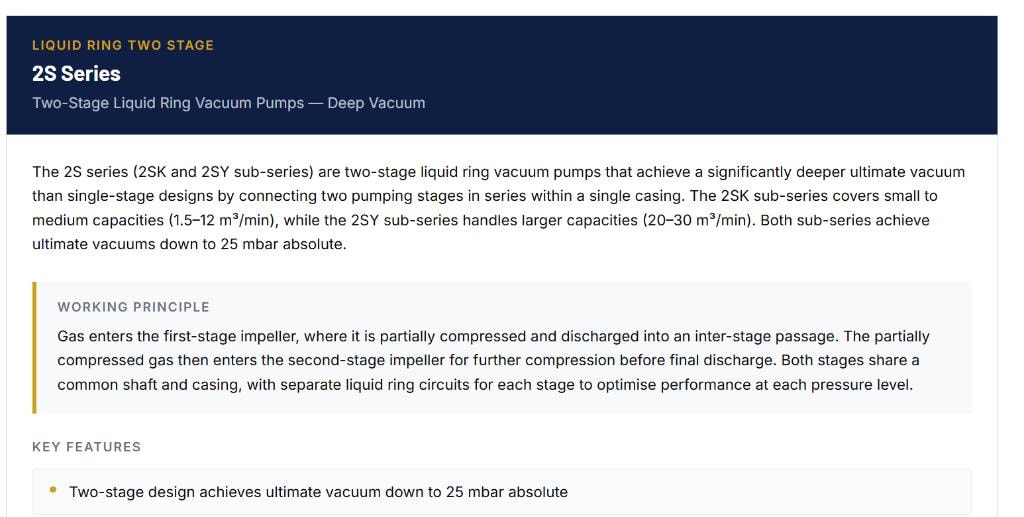
"Central vacuum system" describes the system architecture — the arrangement of vacuum generation, distribution and control. It does not specify one particular vacuum-generation technology.
For relatively low-vacuum, high-flow industrial suction applications (for example, material conveying, low-pressure negative-pressure systems, or some packaging applications), a blower-type or positive-displacement vacuum source may sometimes be appropriate. These machines can move large volumes of gas at modest vacuum levels with reasonable efficiency.
For lower absolute pressures or different process conditions, other technologies may be more appropriate:
- Oil-free claw vacuum pumps — clean, dry operation for many industrial applications
- Rotary vane vacuum pumps — established technology for a wide range of industrial vacuum duties
- Liquid ring vacuum pumps — particularly useful for wet processes, condensable vapor and some contaminated gas streams
- Dry screw vacuum pumps — oil-free, suitable for deeper vacuum and process-compatible applications
- Roots booster + backing pump systems — for lower absolute pressures or high pumping speed at medium vacuum
Do not select the central vacuum source by simply adding the motor powers or nominal capacities of the existing individual pumps.
First determine:
- Required absolute pressure at the process
- Actual airflow (pumping speed) at that pressure
- Simultaneous demand across all users
- Gas composition and any condensable vapor
- Process conditions (temperature, contamination, corrosion)
Then select the vacuum-generation technology accordingly.
Why Motor Power Alone Cannot Size a Central Vacuum System
A common mistake is reasoning as follows:
"We currently have ten 2.2 kW pumps, so we need one 22 kW central pump."
This is not a valid sizing method for several reasons:
- Required operating absolute pressure — the central pump must achieve the required vacuum level at the process, not just at its own inlet
- Pumping speed at that pressure — two pumps with the same motor rating can have very different pumping-speed curves at the same suction pressure
- Simultaneous process demand — if not all workstations operate at the same time, the required central capacity may be less than the sum of individual capacities
- Leakage and intentional air admission — these add to the gas load and must be included
- Duty cycle — intermittent processes require different sizing than continuous ones
- Pressure recovery requirement — how quickly must the system recover after a large demand event?
- Piping pressure loss — the pump must overcome distribution losses in addition to the process vacuum requirement
- Process gas characteristics — condensable vapor, corrosive gases or particulates affect pump selection
- Redundancy — standby capacity may be required
Two vacuum pumps with similar motor ratings can have very different pumping-speed curves at the same suction pressure. Selection must be based on the pump's actual performance curve at the required operating absolute pressure.
Vacuum Piping Can Determine Whether the System Works
A central vacuum system can fail to deliver adequate vacuum at distant workstations even when the central pump is correctly sized — if the distribution piping is undersized or poorly designed.
Pressure loss in vacuum distribution piping depends on:
- Main header diameter — undersized headers cause high velocity and significant pressure loss
- Branch pipe diameter — each branch must be sized for its individual flow
- Pipe length — longer runs increase pressure loss
- Elbows and restrictions — each fitting adds resistance
- Valve sizing — isolation and control valves must be sized for vacuum service
- Filter pressure drop — inlet filters and separators add to the total pressure loss
- Gas flow rate — higher flow means higher velocity and higher pressure loss
- Operating pressure — at lower absolute pressures, gas density decreases and velocity increases for the same mass flow
A pump can achieve the required pressure at its own inlet while a distant workstation receives insufficient vacuum because of distribution pressure loss. Pressure measurement location matters. The control system should measure pressure at the common header or at a representative point in the distribution system — not only at the pump inlet.
Leakage Is Part of the Gas Load
In any vacuum distribution system, leakage is a real and often underestimated gas load. Sources include:
- Pipe joints and flanges
- Flexible hoses and connections
- Vacuum cups (which rarely seal perfectly)
- Valves and actuators
- Seals on process equipment
- Filters and separators
- Unused branches left open or with leaking isolation valves
Leakage adds directly to the pumping speed requirement. A system with significant leakage requires a larger central vacuum station to maintain the required header pressure.
Oversizing the vacuum station is not the correct primary solution to uncontrolled leakage. Leakage should be identified, measured and reduced through proper system design, maintenance and leak detection. Oversizing to compensate for leakage increases capital cost, energy consumption and maintenance burden.
Choosing the Vacuum Pump Technology
Oil-Free Claw Vacuum Pumps
Oil-free claw vacuum pumps use two claw-shaped rotors that rotate without contact, producing a dry, oil-free vacuum. They are well suited to clean industrial applications where oil contamination of the process gas is unacceptable, and where a moderate vacuum level (typically down to approximately 100 mbar(abs) or lower depending on the design) is required.
Claw pumps require no oil in the compression chamber, which simplifies maintenance and eliminates the need for oil mist separators on the exhaust. They are appropriate for many central vacuum applications in food processing, packaging, electronics and general industry.
Rotary Vane Vacuum Pumps
Rotary vane vacuum pumps are an established technology for industrial vacuum generation across a wide range of applications. Oil-lubricated designs provide good ultimate vacuum and reliable performance, but require oil management, exhaust filtration and attention to oil carryover.
In central vacuum applications, rotary vane pumps are suitable for many general industrial duties. Contamination of the process gas with oil vapor must be considered where process purity is important. Exhaust oil mist separators are standard for oil-lubricated designs.
Liquid Ring Vacuum Pumps
Liquid ring vacuum pumps can be particularly useful for wet processes, condensable vapor and some contaminated or corrosive gas streams. The liquid ring (typically water) acts as both the sealing medium and a heat sink, allowing the pump to handle gas streams that would damage dry vacuum pumps.
Performance depends on seal-liquid temperature and vapor pressure. As seal-liquid temperature increases, the vapor pressure of the liquid rises, which limits the achievable vacuum. Seal-liquid cooling is often required to maintain performance.
For clean, relatively low-vacuum, high-airflow duties, alternative vacuum technologies should also be evaluated at the actual duty point.
Dry Screw Vacuum Pumps
Dry screw vacuum pumps use two intermeshing screw rotors to compress gas without oil in the compression chamber. They can achieve deeper vacuum than claw pumps and are suitable for process applications where oil-free operation and chemical compatibility are required.
Dry screw pumps are appropriate where the process gas contains solvents, condensable vapors or chemically aggressive components that would degrade oil-lubricated pumps. The screw profile can be designed to handle condensation within the pump.
Roots Booster Vacuum Systems
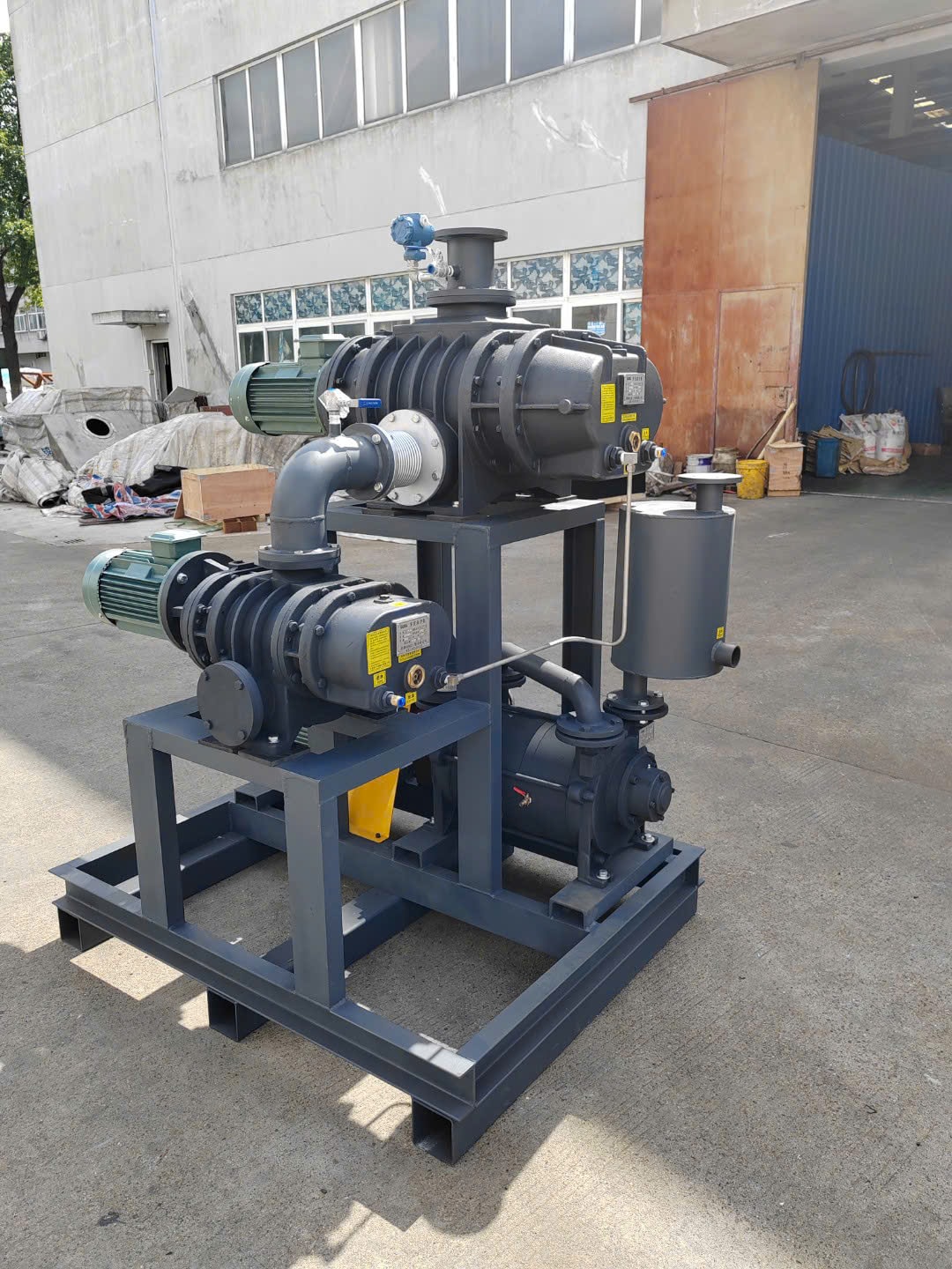
A Roots booster vacuum system combines a Roots blower with an appropriate backing pump. The Roots booster provides high pumping speed at low absolute pressures, while the backing pump handles the final compression to atmospheric pressure.
A conventional Roots booster cannot start from atmospheric pressure and cannot operate without a backing pump maintaining the discharge pressure within the booster's differential pressure limit. The backing pump must first evacuate the system to the Roots booster's starting pressure before the booster is engaged.
When a process requires lower absolute pressure or different pumping-speed characteristics, the vacuum-generation technology may be very different from that used for low-vacuum central suction.
Condensable Vapor Can Change the Selection
When the process gas contains condensable vapor — steam, solvent vapor, or other condensable components — the vacuum pump selection and system design must account for this.
Key factors include:
- Vapor composition and mass flow — what vapor is present and how much?
- Inlet temperature — higher inlet temperature means more vapor in the gas stream
- Cooling conditions — can the vapor be condensed before entering the pump?
- Condensation inside the pump — can the selected pump tolerate liquid formation?
- Operating pressure — at lower absolute pressures, vapor partial pressure becomes a larger fraction of total pressure
- Corrosion — condensed vapor may be corrosive to pump materials
- Downstream treatment — condensate and exhaust gas may require treatment before discharge
An upstream condenser may reduce the vapor load on the vacuum pump where this is technically and economically appropriate. This can allow a smaller pump to be selected and may protect the pump from condensation damage.
For liquid ring vacuum pumps, seal-liquid temperature directly affects the achievable vacuum. As seal-liquid temperature rises, the vapor pressure of the seal liquid increases, raising the minimum achievable absolute pressure. Seal-liquid cooling is typically required to maintain rated performance.
Do not confuse a pump's ultimate vacuum (measured under laboratory conditions with dry air or nitrogen) with the actual operating vacuum achievable under process conditions with condensable vapor present.
When Does a Central Vacuum System Make Sense?
Centralization is worth evaluating when:
- Many machines require similar vacuum pressure levels
- Demand varies significantly over time
- Not all users operate simultaneously at full load
- Individual pumps run during idle periods, consuming energy without useful output
- Distributed maintenance across many pump locations is difficult or costly
- Noise and heat near operators is undesirable
- Redundancy is required and is more economically provided centrally
- Future expansion of vacuum users is expected
When Are Individual Pumps Better?
Individual pumps may be preferable when:
- Only one or two vacuum users exist — centralization adds complexity without benefit
- Workstations require substantially different pressure levels that cannot be served from a common header
- Process gases are incompatible and must not be mixed
- Contamination isolation between workstations is critical
- Piping distances are excessive, making distribution pressure loss prohibitive
- Specialized pump requirements (e.g., ATEX, specific materials) differ between workstations
- Existing dedicated pumps are efficient and well-maintained
Some facilities benefit from a hybrid architecture: a central vacuum system serves the majority of workstations with similar requirements, while one or two specialized workstations retain dedicated pumps.
Recommended Engineering Approach
Before selecting a system architecture, determine:
- Operating absolute pressure — at the process, not at the pump inlet
- Required pumping speed — at the operating absolute pressure
- Number of vacuum users — and their individual requirements
- Simultaneous demand — what fraction of users operate at the same time?
- Gas composition — air, process gas, condensable vapor, corrosive components?
- Duty cycle — continuous, intermittent, batch?
- Altitude and site conditions — affects atmospheric pressure and therefore gauge-to-absolute conversion
- Piping layout — distances, routing, pressure loss budget
- Redundancy requirement — what happens if the vacuum source fails?
Use the vacuum pump selector to identify pump series that match your duty point, or provide these parameters directly to an application engineer for a system recommendation.
Common Mistakes
| Mistake | Why It Matters |
|---|---|
| Adding all existing pump nameplate capacities | Ignores load diversity; typically oversizes the central system |
| Selecting by motor kW | Motor power does not determine pumping speed at the required pressure |
| Ignoring piping pressure loss | Distant workstations may receive insufficient vacuum |
| Ignoring leakage | Leakage adds directly to the required pumping capacity |
| Comparing pumps only by ultimate vacuum | Ultimate vacuum is measured under ideal conditions, not at the process duty point |
| Mixing gauge and absolute pressure | Leads to incorrect pump selection and system sizing |
| Assuming one pump technology is always better | Technology selection depends on the actual duty point and process conditions |
| Ignoring condensable vapor | Can cause pump damage, reduced performance or incorrect sizing |
Frequently Asked Questions
Is a central vacuum system always more energy efficient?
No. Energy efficiency depends on load diversity, operating pressure, pump efficiency at that pressure, control strategy and leakage. If all workstations operate simultaneously at full load, a central system may offer little energy advantage. The calculation must reflect the actual process profile.
Can multiple vacuum pumps use one pressure signal?
A single pressure transmitter on the common header can provide the process variable for a multi-pump control system. However, the control system must be properly designed to handle pump sequencing, protection, alarms and interlocks — not just on/off switching based on one signal.
Should vacuum pressure be specified as gauge or absolute?
For vacuum pump selection, absolute pressure (kPa(abs), mbar(abs) or Pa(abs)) is strongly recommended. Gauge vacuum readings depend on local atmospheric pressure, which varies with altitude and weather. Absolute pressure removes this ambiguity.
Can a liquid ring vacuum pump be used in a central vacuum system?
Yes. Liquid ring pumps are used in central vacuum systems for wet processes, condensable vapor applications and some contaminated gas streams. Performance depends on seal-liquid temperature and vapor pressure. For clean, dry, low-vacuum, high-flow duties, other technologies should also be evaluated.
Does a central vacuum system need a receiver?
Not always. A receiver (vacuum buffer vessel) can stabilize header pressure, reduce pump cycling frequency and provide a short-term reserve during demand peaks. Whether a receiver is required depends on the process demand profile, pump control strategy and acceptable pressure variation. It is not universally necessary.
Can ten small vacuum pumps simply be replaced by one large pump?
Not without a proper engineering evaluation. The replacement pump must achieve the required absolute pressure at the required pumping speed, accounting for simultaneous demand, leakage, piping pressure loss and process conditions. Motor power alone is not a valid sizing criterion.
Conclusion
The correct starting question when evaluating vacuum generation for multiple workstations is not:
"How many kilowatts of vacuum pumps are currently installed?"
It is:
"What absolute pressure and pumping speed does the process actually require, and how does that demand change over time?"
A central vacuum system is a system architecture, not a specific pump type. For relatively low-vacuum, high-flow applications, a blower-type vacuum source may be appropriate. For other pressure ranges or process conditions, claw, rotary vane, liquid ring, dry screw or Roots-based systems may be more suitable. Selection must be based on the actual operating absolute pressure, required pumping speed, gas load and process conditions — evaluated at the real duty point, not at nameplate ratings.
Need help evaluating a central vacuum system for a similar process? Send ZT Pumps your required operating pressure, pumping-speed requirement, number of vacuum users, simultaneous demand, gas composition and process conditions for an engineering recommendation.
Not sure which vacuum pump technology fits your duty point? Use the vacuum pump selector.
Explore Topics
Written by
Zhongtian Pumps Engineering Team
The Zhongtian Pumps Engineering Team specializes in industrial vacuum pump manufacturing, application engineering and vacuum system design. Nantong Zhongtian Machinery Manufacturing Co., Ltd. has manufactured industrial vacuum equipment since 2002.